


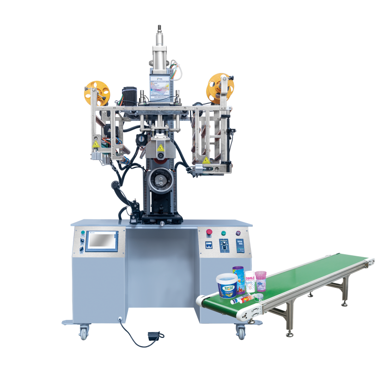
Heat transfer machines are critical equipment in textile printing, garment decoration, and industrial labeling applications, enabling precise transfer of designs onto various substrates through controlled heat and pressure application. When these machines malfunction, production lines slow down, quality deteriorates, and operational costs escalate rapidly. Understanding how to diagnose and resolve common faults such as uneven heating, insufficient pressure, temperature inconsistencies, and control system failures is essential for maintaining productivity and ensuring consistent output quality in manufacturing environments.
This comprehensive troubleshooting guide addresses the most frequently encountered problems that operators and maintenance technicians face with heat transfer machines. By systematically examining fault symptoms, identifying root causes, and implementing targeted corrective measures, you can minimize downtime, extend equipment lifespan, and maintain the transfer quality that your production demands. Whether you're dealing with patchy print results, inadequate bonding strength, or erratic temperature behavior, the diagnostic frameworks and practical solutions presented here will help you restore your heat transfer machine to optimal working condition efficiently.
Understanding Uneven Heating Problems in Heat Transfer Machines
Identifying Uneven Heating Patterns and Their Visual Indicators
Uneven heating manifests as inconsistent transfer results across the working surface of your heat transfer machine, typically appearing as darker and lighter patches, incomplete design transfer in specific zones, or variations in adhesion quality from center to edges. These patterns often reveal themselves immediately during quality inspection when transferred graphics show intensity differences or when adhesive backing fails to bond uniformly across the substrate. Operators frequently notice that certain areas of the platen consistently produce inferior results regardless of substrate positioning, indicating systematic heating irregularities rather than random process variations.
The spatial distribution of heating problems provides diagnostic clues about underlying causes. Edge cooling occurs when perimeter zones receive insufficient thermal energy compared to central regions, typically resulting from heat dissipation to surrounding cooler components or inadequate insulation. Conversely, hot spots concentrated in specific areas suggest localized heating element damage, uneven element distribution, or thermal sensor calibration drift that causes the control system to deliver excessive energy to particular zones while starving others.
Visual inspection techniques help identify uneven heating before it severely impacts production quality. Thermal imaging cameras reveal temperature distribution patterns across the platen surface during operation, making invisible thermal gradients visible and quantifiable. Temperature-sensitive strips or thermal papers placed across the working surface during test cycles provide cost-effective mapping of heating uniformity, changing color in proportion to experienced temperature and creating a permanent record of thermal distribution for comparison over time.
Root Causes of Heating Element Degradation and Malfunction
Heating elements in your heat transfer machine degrade through several mechanisms that compromise thermal output uniformity. Resistive heating wires develop localized resistance increases from oxidation, physical stress, or manufacturing defects, causing reduced current flow and diminished heat generation in affected sections. Over extended operating periods, thermal cycling stresses cause micro-cracks in heating element conductors, progressively reducing their effective cross-sectional area and increasing electrical resistance in damaged zones while adjacent undamaged sections continue operating normally.
Electrical connection deterioration at heating element terminals represents another common failure mode affecting heating uniformity. Thermal expansion and contraction cycles gradually loosen terminal connections, increasing contact resistance and generating localized heating at connection points rather than throughout the intended heating zone. Oxidation and contamination at these interfaces further increase resistance, eventually creating high-resistance connections that divert electrical energy into unproductive heating at terminals while reducing power delivery to the working element sections.
Insulation breakdown within heating assemblies allows thermal energy to escape through unintended pathways, reducing the energy available for substrate heating and creating localized cool zones. Compressed or damaged insulation materials lose their thermal resistance properties, permitting heat conduction to the machine frame or surrounding components. Moisture intrusion into insulation layers dramatically accelerates thermal conductivity, creating thermal short-circuits that rob heat from the working surface and establish persistent cold spots that resist correction through simple temperature adjustments.
Thermal Sensor Calibration Drift and Its Impact on Temperature Control
Temperature sensors in heat transfer machines gradually drift from their factory calibration due to aging effects, thermal shock exposure, and environmental contamination, causing the control system to maintain incorrect setpoints despite displaying accurate target values. A sensor reading low relative to actual temperature causes the controller to deliver excessive heating power in attempts to reach the displayed setpoint, creating overheating conditions that damage substrates and transferred materials. Conversely, sensors reading high cause under-heating, resulting in incomplete transfer adhesion and poor image quality.
Multi-zone heat transfer machines with independent temperature control for different platen areas become particularly susceptible to uneven heating when sensors drift at different rates. One zone's sensor may drift upward while another drifts downward, causing the control system to create intentional but incorrect temperature differentials across the working surface. Regular calibration verification using traceable reference thermometers identifies sensor drift before it significantly impacts process quality, allowing preventive recalibration or replacement rather than reactive troubleshooting after quality problems emerge.
Sensor placement accuracy critically influences temperature control effectiveness in your heat transfer machine. Sensors installed too far from the working surface or in thermally isolated pockets measure temperatures that poorly represent actual substrate contact conditions, causing control systems to respond incorrectly to process demands. Thermal paste degradation between sensors and mounting surfaces creates thermal resistance that delays sensor response and reduces measurement accuracy, effectively decoupling the control system from actual thermal conditions and permitting temperature excursions before corrective action initiates.
Diagnosing and Resolving Insufficient Pressure Issues
Pressure Generation System Components and Failure Modes
The pressure generation system in your heat transfer machine converts mechanical or pneumatic/hydraulic force into the uniform contact pressure essential for successful transfer adhesion. Pneumatic systems rely on compressed air cylinders that develop force proportional to air pressure and piston area, while hydraulic systems use incompressible fluid to generate higher pressures with smaller actuators. Manual mechanical systems employ leverage mechanisms, springs, or screw-driven presses to create clamping force through operator input or motorized drives.
Insufficient pressure typically originates from degraded force generation capacity, force transmission losses, or inadequate pressure distribution across the contact surface. Pneumatic cylinder seals wear progressively, allowing pressurized air to bypass the piston rather than generating full rated force, with wear rates accelerating when contaminated air introduces abrasive particles or when inadequate lubrication permits dry sliding contact. Hydraulic seal deterioration similarly reduces pressure generation capacity while creating fluid leakage that gradually depletes system pressure during the dwell cycle.
Mechanical linkage wear in lever-based pressure systems introduces slack and compliance that absorbs applied force before it reaches the platen assembly. Pivot bearings develop clearances from wear, springs lose tension from fatigue and stress relaxation, and structural members deflect elastically under load rather than rigidly transmitting force. These cumulative effects reduce effective pressure at the work surface even when actuator force remains nominally adequate, requiring systematic inspection of the entire force transmission path from generation point to contact surface.
Pressure Distribution Problems and Platen Surface Conditions
Even when your heat transfer machine generates adequate total clamping force, non-uniform pressure distribution across the contact surface produces localized insufficient pressure zones that compromise transfer quality. Platen surface flatness deviations concentrate pressure on high spots while leaving recessed areas with inadequate contact force, creating corresponding variations in transfer adhesion and image density. Manufacturing tolerances, thermal distortion, and mechanical wear progressively degrade initial flatness, with thermal cycling causing particularly severe distortion in inadequately designed platens.
Resilient pressure pad degradation represents a critical but often overlooked cause of pressure distribution problems. Silicone or foam pads that compensate for minor surface irregularities and substrate thickness variations lose compliance through thermal aging, compression set, and chemical exposure to solvents or plasticizers from transfer materials. Hardened pads no longer conform to surface contours, instead bridging across low areas and concentrating pressure on contact peaks, effectively amplifying rather than compensating for flatness errors.
Contamination buildup on platen surfaces creates localized high spots that disrupt pressure distribution patterns across your heat transfer machine working area. Adhesive residue, substrate fibers, and degraded transfer material accumulate preferentially in high-temperature zones, forming hard deposits that elevate local surface height and concentrate pressure. Regular cleaning protocols prevent buildup accumulation, but established contamination often requires mechanical removal with appropriate solvents and non-abrasive techniques to avoid damaging precision-finished platen surfaces.
Pneumatic and Hydraulic System Diagnostics
Systematic diagnosis of pneumatic pressure systems begins with supply pressure verification at the heat transfer machine inlet, ensuring adequate pressure availability before investigating downstream components. Pressure gauges installed at cylinder ports during operation reveal pressure losses through supply lines, valves, and fittings, with significant pressure drops indicating flow restrictions from undersized components, contamination blockages, or damaged hoses. Cylinder force output testing under load conditions distinguishes between supply pressure deficiencies and cylinder-specific problems such as seal leakage or piston binding.
Hydraulic system diagnosis requires pressure testing throughout the circuit from pump output through control valves to actuator ports, identifying pressure losses and verifying pump delivery capacity under operating loads. Hydraulic fluid condition assessment reveals contamination, water intrusion, or chemical degradation that compromises system performance through increased internal leakage, accelerated component wear, or altered fluid properties. Actuator stroke consistency measurements detect internal leakage across piston seals, with progressively increasing stroke requirements to achieve target pressure indicating seal deterioration requiring replacement.
Air or fluid leakage detection employs acoustic methods for pneumatic systems, where ultrasonic detectors identify high-frequency sound emissions from pressurized air escaping through seal defects or fitting leaks. Hydraulic systems require visual inspection under pressure for external leaks combined with performance testing to detect internal leakage across valve seats or cylinder seals. Pressure decay testing with actuators locked in position quantifies total system leakage, with acceptable decay rates depending on system design but typically not exceeding specified limits that ensure adequate dwell pressure maintenance throughout transfer cycles.
Addressing Temperature Control System Malfunctions
Control System Architecture and Failure Point Identification
Modern heat transfer machine temperature control systems integrate sensors, controllers, power switching devices, and heating elements into closed-loop feedback systems that maintain setpoint temperatures despite process load variations. Proportional-integral-derivative controllers adjust heating power based on temperature error magnitude, error duration, and error rate of change, providing responsive yet stable temperature regulation. System malfunctions occur when any component in this control loop fails, introducing errors that cascade through the feedback mechanism and produce symptoms ranging from minor temperature instability to complete control loss.
Sensor circuit faults manifest as temperature reading errors, erratic displays, or complete signal loss that prevents proper control action. Open sensor circuits typically drive displays to minimum or maximum readings depending on controller design, while short circuits may produce intermediate but incorrect values that appear plausible but cause systematic control errors. Electrical noise from nearby power circuits or radio-frequency sources can induce spurious signals in sensor wiring, particularly with high-impedance thermocouple circuits, causing temperature reading fluctuations that produce unstable control behavior.
Power switching component failures in your heat transfer machine control system prevent proper heating power modulation despite correct controller outputs. Solid-state relays degrade through thermal cycling and electrical stress, developing increased on-state resistance that reduces heating power or failing in shorted conditions that apply continuous maximum power regardless of control signals. Mechanical contactors wear through repeated switching cycles, developing contact resistance, welding closed, or failing to close reliably, with failure modes producing corresponding effects on temperature control capability.
Temperature Overshoot and Oscillation Problems
Temperature overshoot occurs when your heat transfer machine exceeds setpoint temperature during initial heating or after process disturbances, potentially damaging temperature-sensitive substrates or transferred materials. Excessive controller gain settings cause aggressive heating that overshoots target temperatures before feedback correction can respond, while insufficient integral action allows sustained offset errors that persist after initial overshoot correction. Thermal mass mismatch between heating elements and temperature sensors creates response delays, with sensors measuring temperature changes significantly later than they occur at the substrate contact surface.
Oscillating temperature control produces cyclic variations around the setpoint rather than stable regulation, appearing as regular fluctuations in temperature displays and corresponding variations in transfer quality. Excessive proportional gain relative to system time constants causes over-correction that drives temperature alternately above and below target, with oscillation frequency inversely related to thermal mass and control loop response time. Mechanical relay switching combined with insufficient controller deadband creates oscillation as the relay cycles rapidly on and off around the setpoint, visible as relay chatter and corresponding temperature fluctuations.
Proper controller tuning eliminates most overshoot and oscillation problems in heat transfer machines through systematic adjustment of proportional, integral, and derivative parameters. Auto-tuning functions in modern controllers automatically determine optimal parameters by analyzing system response to controlled disturbances, though manual tuning may achieve superior results when operators understand process-specific requirements. Conservative tuning with lower gains and slower response reduces overshoot and oscillation at the cost of slower setpoint acquisition and reduced disturbance rejection, requiring balance between stability and performance based on application demands.
Electrical Connection and Power Supply Integrity
Electrical connection integrity throughout your heat transfer machine power and control circuits critically affects system reliability and performance. Terminal block connections carrying heating element current develop resistance from loosening, oxidation, or thermal cycling stress, generating localized heating that further accelerates connection degradation and eventually causes complete circuit failure. Periodic connection inspection and retorquing according to manufacturer specifications prevents progressive loosening, while contact cleaning maintains low-resistance interfaces that minimize power losses and connection heating.
Power supply voltage stability and capacity directly influence heating element performance and control system operation. Insufficient supply capacity causes voltage sag under load, reducing heating power below rated values and extending heating times or preventing setpoint achievement. Voltage fluctuations from facility electrical system disturbances create corresponding heating power variations that control systems cannot fully compensate, producing temperature instability despite properly functioning control components. Power quality monitoring identifies supply-related problems that require correction at facility level rather than equipment level.
Ground connection integrity affects both safety and noise immunity in heat transfer machine electrical systems. Inadequate grounding permits chassis voltage rise during ground fault conditions, creating shock hazards and potential equipment damage from fault currents flowing through unintended paths. Poor grounding also compromises electrical noise immunity by eliminating the stable reference potential required for proper sensor signal transmission, allowing common-mode noise voltages to corrupt measurement signals and cause erratic control behavior that appears similar to sensor or controller malfunctions.
Preventive Maintenance Strategies for Fault Prevention
Scheduled Inspection and Cleaning Protocols
Implementing systematic inspection schedules prevents most common heat transfer machine faults through early detection and correction of degradation before failures occur. Daily visual inspections identify obvious problems such as loose connections, fluid leaks, or damaged components that require immediate attention, while weekly detailed inspections examine critical systems including heating elements, pressure mechanisms, and control components for subtle degradation signs. Monthly comprehensive inspections incorporate measurement-based assessments such as temperature calibration verification, pressure output testing, and electrical connection resistance measurements that quantify system condition and track deterioration trends.
Cleaning protocols tailored to your heat transfer machine operating environment prevent contamination-related failures and maintain optimal performance. Platen surface cleaning removes adhesive residue, substrate fibers, and degraded transfer material that compromise heat transfer efficiency and pressure distribution uniformity. Cooling system cleaning eliminates dust and lint accumulation on heat exchangers and fan blades that reduces cooling capacity and permits thermal component overheating. Electrical cabinet cleaning prevents dust buildup that promotes electrical tracking, reduces cooling airflow, and provides combustible material that increases fire risk.
Lubrication maintenance according to manufacturer specifications ensures smooth operation of mechanical components and prevents premature wear failures. Pneumatic cylinder rod seals require appropriate lubricants to minimize friction and prevent dry sliding that rapidly degrades seals, while mechanical linkage pivots need regular lubrication to maintain low friction and prevent galling. However, excessive lubrication proves counterproductive by attracting contamination, migrating onto heated surfaces where it degrades and forms deposits, or interfering with pneumatic seal function through viscosity effects at elevated temperatures.
Component Replacement Criteria and Lifecycle Management
Establishing evidence-based component replacement criteria prevents unexpected failures through proactive replacement before end-of-life failure occurs. Heating elements exhibit predictable degradation patterns with resistance increasing and heating uniformity deteriorating over operational hours, allowing replacement scheduling based on usage accumulation or performance degradation thresholds. Temperature sensors similarly degrade predictably, with thermocouple drift rates and resistance temperature detector stability specifications enabling replacement scheduling that prevents calibration drift from affecting product quality.
Wear component identification and lifecycle tracking focuses maintenance resources on items with limited service life that require regular replacement regardless of apparent condition. Pneumatic and hydraulic seals fall into this category, exhibiting elastomer aging that progresses independently of visible wear and eventually causes sudden seal failure after extended service periods. Resilient pressure pads similarly age through thermal exposure and compression cycling, losing compliance and requiring replacement on time-based schedules rather than waiting for obvious performance degradation.
Critical spare parts inventory management ensures rapid fault correction when failures occur despite preventive maintenance efforts. High-failure-rate components, long-lead-time items, and parts critical to heat transfer machine operation warrant inventory investment to minimize downtime costs that typically far exceed spare parts carrying costs. Manufacturer-recommended spare parts lists provide starting points for inventory development, with customization based on actual failure experience and specific application operating severity producing optimized inventories that balance investment against downtime risk.
Operator Training and Operational Best Practices
Comprehensive operator training significantly reduces fault occurrence by ensuring proper equipment operation and enabling early problem detection before minor issues escalate into major failures. Training programs should cover correct startup and shutdown procedures that minimize thermal and mechanical shock to components, proper parameter settings for different substrate types and transfer materials, and recognition of abnormal operating symptoms that indicate developing problems requiring maintenance attention. Operators familiar with equipment capabilities and limitations avoid operating practices that overstress components or operate outside design envelopes.
Process parameter documentation and standardization eliminate trial-and-error operation that causes unnecessary equipment stress and inconsistent results. Documented parameter sets for each substrate and transfer material combination provide repeatable settings that achieve quality results without excessive temperature or pressure that accelerates component wear. Parameter change logging enables correlation between operating condition modifications and subsequent equipment problems, supporting root cause analysis when faults occur and preventing recurrence through parameter restriction or equipment design modification.
Operational discipline regarding warm-up procedures, cycle timing, and production scheduling protects your heat transfer machine from thermal shock and mechanical overload. Gradual temperature ramping during startup prevents thermal stress from rapid heating, while adequate soak time at operating temperature ensures thermal equilibrium throughout the platen assembly before production begins. Cycle timing discipline prevents pressure system overwork from excessively rapid cycling that allows insufficient cooling between cycles, while production scheduling avoids extended continuous operation that prevents periodic cooling and inspection during natural production breaks.
FAQ
What causes one corner of my heat transfer machine platen to be significantly cooler than the others?
A persistently cool corner typically indicates either a failed heating element section in that zone, a loose electrical connection reducing power delivery to that area, or damaged insulation allowing excessive heat escape through the machine frame. Thermal imaging will confirm the temperature differential, after which electrical resistance testing of heating element sections and terminal connections will identify whether the problem is electrical. If electrical testing shows normal values, the insulation beneath the platen in that corner has likely compressed or deteriorated and requires replacement to restore thermal performance.
How can I tell if insufficient pressure is caused by the pneumatic cylinder or the pressure pad?
Perform a force measurement test by placing a calibrated force gauge or pressure-sensitive film between the platens and measuring actual contact force across multiple locations. If force readings are uniformly low across the entire surface, the pneumatic cylinder is not generating adequate force, likely from seal leakage or insufficient supply pressure. If force varies significantly across the surface with some areas adequate and others deficient, the pressure pad has hardened or degraded and no longer distributes force uniformly, requiring pad replacement rather than cylinder repair.
Why does my heat transfer machine temperature fluctuate by 10-15 degrees even though the controller shows stable setpoint?
Temperature oscillation of this magnitude usually results from incorrect controller tuning parameters, particularly excessive proportional gain that causes over-correction, or a failing solid-state relay that switches erratically. Check whether the oscillation period is regular and consistent, suggesting a tuning problem, or irregular and random, indicating component failure. Additionally, verify that the temperature sensor maintains good thermal contact with the platen through intact thermal paste or mechanical clamping, as poor sensor coupling creates measurement delays that cause control instability even with correct tuning parameters.
What maintenance interval should I follow for replacing pressure pads and heating elements in industrial production environments?
Pressure pad replacement intervals depend heavily on operating temperature and production volume but typically range from 6 to 18 months in continuous industrial use, with pads used at higher temperatures requiring more frequent replacement due to accelerated thermal aging. Monitor pad condition through hardness testing or transfer quality assessment rather than relying solely on time intervals. Heating elements in properly designed systems typically last 3 to 5 years under normal industrial conditions, though harsh environments with thermal cycling, contamination, or electrical supply instability may reduce lifespan to 1 to 2 years, making condition-based replacement through periodic resistance testing more reliable than fixed time schedules.
Table of Contents
- Understanding Uneven Heating Problems in Heat Transfer Machines
- Diagnosing and Resolving Insufficient Pressure Issues
- Addressing Temperature Control System Malfunctions
- Preventive Maintenance Strategies for Fault Prevention
-
FAQ
- What causes one corner of my heat transfer machine platen to be significantly cooler than the others?
- How can I tell if insufficient pressure is caused by the pneumatic cylinder or the pressure pad?
- Why does my heat transfer machine temperature fluctuate by 10-15 degrees even though the controller shows stable setpoint?
- What maintenance interval should I follow for replacing pressure pads and heating elements in industrial production environments?